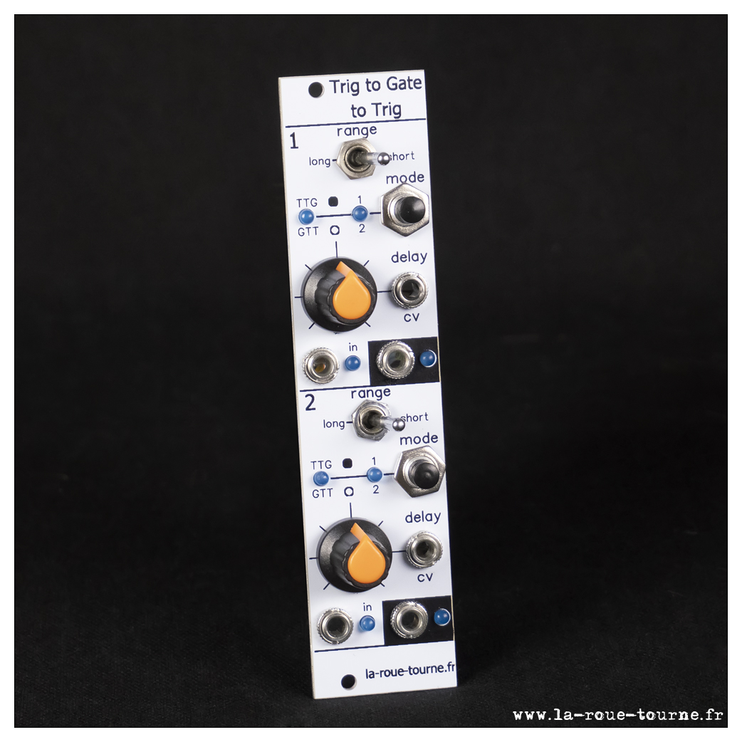
Avant la description, le fonctionnement général est à voir ici :
|
Le circuitA base d'atmega328 comme d'habitude.RésultatLe PCB : double face assez simple. Consommation : +12V = 25 mA ; -12V = 2 mA |
The circuitAtmega328 based as usual. ResultThe PCB: 2 simple layers. |

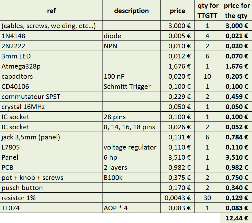
BOM
Code
Le code est divisé en trois sections :
- main :
/* Trigger to Gate to Trigger
   V 0.1 : init
   V 0.2 : 2 leds per channel (TTG & mode)
   V 0.3 : EEPROM saving of presets
   V 0.4 : 2 more modes : random gate & bouncing ball
   V 0.5 : minor modifications + english translation
   V 0.6 : direct port manipulations instead of digitalRead and digitalWrite

   2020 LC  www.la-roue-tourne.fr/index.php/modulaire
  -------------------------------------------------------
  D0: port D bit 0
  D1: port D bit 1
  D2: port D bit 2   IN 1
  D3: port D bit 3   IN 2
  D4: port D bit 4   OUT 1
  D5: port D bit 5   OUT 2
  D6: port D bit 6   SWITCH RANGE 1
  D7: port D bit 7   SWITCH RANGE 2

  D8: port B bit 0    Led 1
  D9: port B bit 1    Led 2
  D10: port B bit 2   Led 3
  D11: port B bit 3   Led 4
  D12: port B bit 4   BP1 with built-in debouncer
  D13: port B bit 5   BP2 with built-in debouncer

  A0: port C bit 0   POT 1
  A1: port C bit 1   CV 1
  A2: port C bit 2   POT 2
  A3: port C bit 3   CV 2
  A4: port C bit 4
  A5: port C bit 5

*/

//  modes
#define TTG 0       // trigger to gate with 2 sub modes
#define GTT 1       // gate to trigger with 2 sub modes
#define RND 2       // random ou bouncing with 2 sub modes

/*  set FIRST_RUN to true for the first time then set it to false
    as it is necessery to have a good EEPROM data set
*/
#define FIRST_RUN   false

// --------------------------------------------------- channels
struct {
  unsigned long startTime;
  int potValue, jackValue;
  int mode, subMode;
  int upDuration;
  int nextBounce;
  int pinInput, pinOutput, pinRange, pinLED_mode, pinLED_subMode, pinPushButton;
  int range;
  int oldState, oldPushButton;
  boolean gateUp, bounceRunning;
} channel[2];

// --------------------------------------------------- potentiometer & switch reading
int potCounter;
unsigned long potDate, buttonDate;

// --------------------------------------------------- blinking LED (RND mode only)
int stateLed;

void setup() {
  int i;

  randomSeed(analogRead(A0) + analogRead(A2));

  channel[0].pinInput = 2;
  channel[1].pinInput = 3;
  channel[0].pinOutput = 4;
  channel[1].pinOutput = 5;
  channel[0].pinRange = 6;
  channel[1].pinRange = 7;
  channel[0].pinLED_mode = 8;
  channel[1].pinLED_mode = 10;
  channel[0].pinLED_subMode = 9;
  channel[1].pinLED_subMode = 11;
  channel[0].pinPushButton = 12;
  channel[1].pinPushButton = 13;

  for (i = 0; i < 2; i++) {
    pinMode(channel[i].pinInput, INPUT_PULLUP);
    pinMode(channel[i].pinRange, INPUT_PULLUP);
    pinMode(channel[i].pinOutput, OUTPUT);
    pinMode(channel[i].pinLED_mode, OUTPUT);
    pinMode(channel[i].pinLED_subMode, OUTPUT);
    pinMode(channel[i].pinPushButton, INPUT_PULLUP);

    channel[i].bounceRunning = false;
    stateLed = 0;
    gateDown(i);
  }

  // before the 1st run, to have a good EEPROM data
  if (FIRST_RUN) {
    for (i = 0; i < 2; i++) {
      channel[i].mode = 0;
      channel[i].subMode = 0;
    }
    saveEEPROM();
  } else {
    loadEEPROM();
  }

  initPot();
  updateLED();
  buttonDate = 0;
}


void loop() {
  unsigned long now = millis();
  int state[2];
  int i;

  // ----------------------------------------- gates
  state[0] = bitRead(PORTD, 2);
  state[1] = bitRead(PORTD, 3);
  for (i = 0; i < 2; i++) {
    if (state[i] != channel[i].oldState) {
      channel[i].oldState = state[i];
      switch (channel[i].mode) {
        case TTG :
          if ((state == HIGH) && ((channel[i].subMode == 1) || (!channel[i].gateUp))) {
            gateUp(i, now);
          }
          break;
        case GTT :
          if (channel[i].subMode == 0) {
            if (state == HIGH) {
              gateUp(i, now);
            }
          } else {
            gateUp(i, now);
          }
          break;
        case RND :
          if (state == HIGH) {
            if (channel[i].subMode == 0) {
              if (random(2046) < channel[i].upDuration) {
                gateUp(i, now);
              }
            } else {
              if (!channel[i].bounceRunning) {
                channel[i].bounceRunning = true;
                gateUp(i, now);
                channel[i].nextBounce = channel[i].upDuration * 0.9;
              }
            }
          }
          break;
      }
    }
  }

  // ----------------------------------------- bounces & triggers' end
  for (i = 0; i < 2; i++) {
    if (channel[i].mode != RND) {
      if (now - channel[i].startTime >= channel[i].upDuration) {
        gateDown(i);
      }
    } else {
      // ----------------------------- these are fixed triggers (30 ms)
      if (now - channel[i].startTime >= 30) {
        gateDown(i);
      }
      // ----------------------------- we are bouncing
      if (channel[i].bounceRunning) {
        if (now - channel[i].startTime >= channel[i].nextBounce) {
          gateUp(i, now);

          channel[i].nextBounce *= 0.9;
          if (channel[i].nextBounce < 30) {
            channel[i].bounceRunning = false;
          }
        }
      }
    }
  }

  // ----------------------------------------- switches & pots & LEDs
  if (now - potDate > 101) {
    potDate = now;
    stateLed = 1 - stateLed;
    updateLED();
    potCounter ++;
    if (potCounter > 5) {
      potCounter = 0;
    }

    switch (potCounter) {
      case 0:
        channel[0].potValue = analogRead(A0);
        updateDuration(0);
        break;
      case 1:
        channel[0].jackValue = analogRead(A1);
        updateDuration(0);
        break;
      case 2:
        channel[1].potValue = analogRead(A2);
        updateDuration(1);
        break;
      case 3:
        channel[1].jackValue = analogRead(A3);
        updateDuration(1);
        break;
      case 4:
        channel[0].range = bitRead(PORTD, 6);
        updateDuration(0);
        break;
      case 5:
        channel[1].range = bitRead(PORTD, 7);
        updateDuration(1);
        break;
    }
  }

  // ----------------------------------------- push buttons
  if (now - buttonDate > 127) {
    buttonDate = now;
    state[0] = bitRead(PORTB, 4);
    state[1] = bitRead(PORTB, 5);
    for (i = 0; i < 2; i++) {
      if (state[i] != channel[i].oldPushButton) {
        channel[i].oldPushButton = state[i];

        // the button is on
        if (state == HIGH) {
          channel[i].subMode ++;
          if (channel[i].subMode > 1) {
            channel[i].subMode = 0;
            channel[i].mode ++;
            if (channel[i].mode > 2) {
              channel[i].mode = 0;
            }
          }
          channel[i].bounceRunning = false;
          saveEEPROM();
        }
      }
    }
  }
}
- Gestion de l'EEPROM :
#include EEPROM.h

/*
 *  IMPORTANT :
 *
 *  mode & subMode are INTs (2-byte long)
 *
 */

void saveEEPROM() {
  int adress = 0;
  for (int i = 0; i < 2; i++) {
    EEPROM.put(adress, channel[i].mode);
    adress += 2;
    EEPROM.put(adress, channel[i].subMode);
    adress += 2;
  }
}
void loadEEPROM() {
  int adress = 0;

  for (int i = 0; i < 2; i++) {
    EEPROM.get(adress, channel[i].mode);
    adress += 2;
    EEPROM.get(adress, channel[i].subMode);
    adress += 2;
  }
}
- I/O :
void gateUp(int numGate, unsigned long dateGateUp) {
  if (numGate == 0) {
    bitSet(PORTD, 4);
  } else {
    bitSet(PORTD, 5);
  }
  channel[numGate].gateUp = true;
  channel[numGate].startTime = dateGateUp;
}

void gateDown(int numGate) {
  if (numGate == 0) {
    bitClear(PORTD, 4);
  } else {
    bitClear(PORTD, 5);
  }
  channel[numGate].gateUp = false;
}

/*
 *  1st pot and switches reading.
 *  Done once, so no need of direct port access
 */
void initPot() {
  potCounter = 0;
  potDate = millis();
  channel[0].potValue = analogRead(A0);
  channel[0].jackValue = analogRead(A1);
  channel[1].potValue = analogRead(A2);
  channel[1].jackValue = analogRead(A3);
  channel[0].range = digitalRead(channel[0].pinRange);
  channel[1].range = digitalRead(channel[1].pinRange);
  updateDuration(0);
  updateDuration(1);
}

void updateDuration(int channelNumber) {
  int duration;
  duration = channel[channelNumber].potValue + (511 - channel[channelNumber].jackValue) * 2;   //  -1024 to 2046
  if (duration < 1) {
    duration = 1;                                                            // 1 to 2046 ms
  }

  if (channel[channelNumber].mode == RND) {              // RND : from 0 to 2046
    channel[channelNumber].upDuration = duration;              // for random & bounce
  } else {

    //                                          other modes : adapting depends on the range (short/long)
    if (channel[channelNumber].range) {
      duration = duration << 2;                       // x4 depending on the range : 4 ms to 8174 ms
    }

    if (channel[channelNumber].mode == TTG) {
      channel[channelNumber].upDuration = duration;                            // gates : 0 to 2 s or 0 to 8 s
    } else {
      channel[channelNumber].upDuration = duration >> 4;                       // trigger : 0 to 128 ms or 0 to 512 ms
    }
  }
}

void updateLED() {
  for (int i = 0; i < 2; i++) {
    if (channel[i].mode == RND) {
      digitalWrite(channel[i].pinLED_mode, stateLed);
    } else {
      digitalWrite(channel[i].pinLED_mode, channel[i].mode);
    }
    digitalWrite(channel[i].pinLED_subMode, channel[i].subMode);
  }
}
- Clics : 10485
Multiple
|
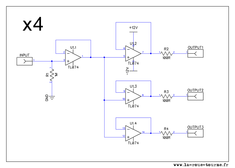
Un petit utilitaire : un quadruple multiple 1->3 alimenté (pas passif). Le schéma est très simple et peut se faire sur une plaque pré-gravée.
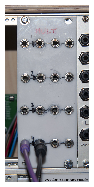
Résultat Je suis le roi du bavage de colle sur la façade en plastique... Réalisé pour un coût total de l'ordre de 8 € |
First module: a quadruple buffered multiple. The schematics is very simple and can be done on a veroboard too
Result Around 8 €, included the glue leaks on the plastic facade! |

Octo-CV
|
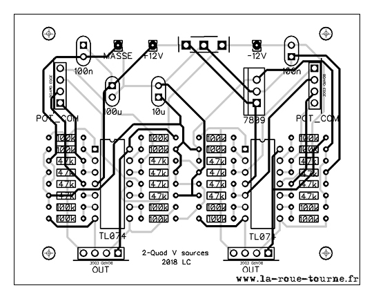
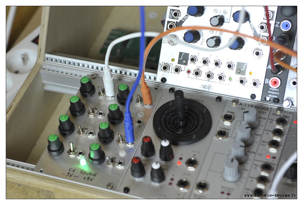
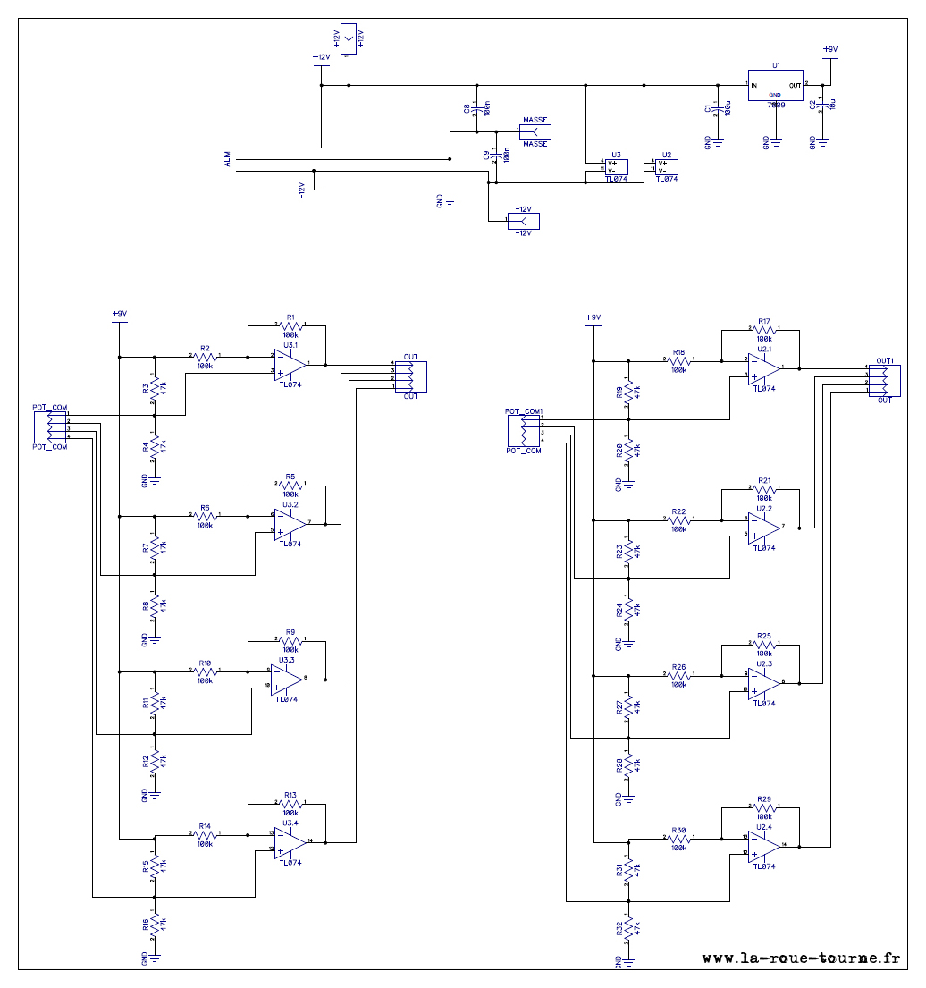
Autre utilitaire : 8 CV réglables de -9V à 9V avec interrupteur. Le principe est adapté du blog Kassutronics, avec une entrée fixe de 9V générée par un 7809. L'intérêt est que la sensibilité du potard n'est pas la même autour de 0 qu'aux extrèmes. En utilisant un autre régulateur positif de la série 78XX, on peut faire varier l'échelle (par exemple de -5V à +5V) Résultat Ci-dessous se trouve mon schéma ainsi que le résultat final (12,50 €). Pour positionner les boutons des potentiomètres, il faut chercher le zéro puis les installer.
|
Other utility module: 8 adjustable CV from -9V to 9V with switch. The schematics is adapted from the blog Kassutronics, with a fixed 9V input generated by a 7809. The interest is that the sensitivity of the knob is not the same around 0 and at the extremes. By using another positive regulator of the 78XX series, it is possible to modify the scale (for example from -5V to + 5V) Result Below is my schematics and the final result, for around 12,50 €. To position the knobs of the potentiometers, it is necessary to look for the zero then to install them. |
- Clics : 2372
Page 3 sur 3


