Avant la description, le fonctionnement général est à voir ici :
Fonctionnement
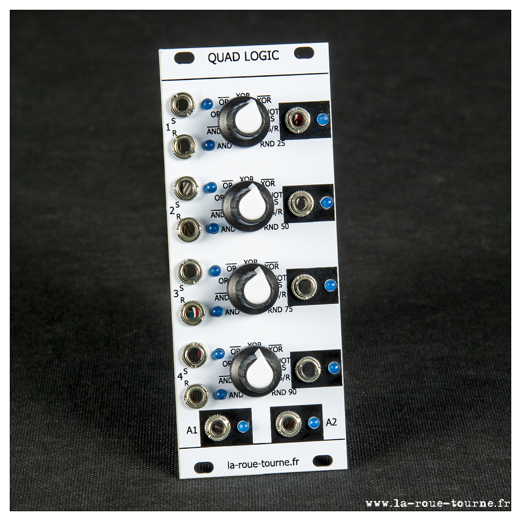
Il existe des schémas basés sur des portes AND, OR etc, mais je voulais quelque chose de simple et de souple : 4 paires d'entrées sont associées à 4 sorties via 8 fonctions logiques indépendantes, et 2 sorties supplémentaires sont disponibles. Au prix des atmega328, c'est même moins cher qu'un montage à base de portes logiques. C'est moins rapide, mais largement suffisant pour mon usage (environ 80 ns) ! L'avantage est que je dispose de 2 sorties programmables selon mes besoins.
Les 9 fonctions sont accessibles indépendamment avec les potards : AND, NAND, OR, NOR, XOR, NXOR, NOT (voie 1), Set/Reset, ALEAS (sur front voie 1).
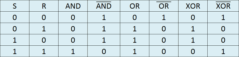
Schéma :
Programme :
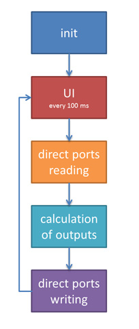
Le code est divisé en trois sections :
- main :
/*

  QuadLogic v0.4

  Laurent Chaté 2019-2020

  www.la-roue-tourne.fr

  4 paires d'entrée sont logiquement liées sur 4 sorties
  à l'aide de 7 opérations logiques + 1 aléas + S/R
  durée d'un cycle complet de scan/calcul/sortie < 80 ns

  -------------------------------------------------------
  D0 : out G1
  D1 : out G2
  D2 : in A1
  D3 : in A2
  D4 : in B1
  D5 : in B2
  D6 : in C1
  D7 : in C2
  D8 : in D1
  D9 : in D2

  D10: out A
  D11: out B
  D12: out C
  D13: out D

  A0 : potard MODE  0 (23)
  A1 : potard MODE  1
  A2 : potard MODE  2
  A3 : potard MODE  3
  A4 : N/A
  A5 : N/A

*/

// entrées
#define pinA1 2
#define pinA2 3
#define pinB1 4
#define pinB2 5
#define pinC1 6
#define pinC2 7
#define pinD1 8
#define pinD2 9

// sorties
#define pinGP1 0
#define pinGP2 1
#define pinA  10
#define pinB  11
#define pinC  12
#define pinD  13

byte pinIn[] = {pinA1, pinA2, pinB1, pinB2, pinC1, pinC2, pinD1, pinD2};
byte entree[8];

byte pinOut[] = {pinA, pinB, pinC, pinD, pinGP1, pinGP2};
byte sortie[4];

// --------------------------------------------------- lecture potentiometres
byte compteurPot;
unsigned long timePot;

// --------------------------------------------------- les modes des 4 voies
enum modes {
  MODE_AND,
  MODE_NAND,
  MODE_OR,
  MODE_NOR,
  MODE_XOR,
  MODE_NXOR,
  MODE_NOT,
  MODE_SR,
  MODE_ALEAS
};

modes mode[4];

// variables temporaires pour la gestion de l'aléas
byte oldX1[4], oldY[4];

// les seuils pour les aléas
int seuil[4] = {25, 50, 75, 90};

void setup() {
  int i;

  initPotard();
  randomSeed(mode[0] + mode[1] + mode[2] + mode[3]);

  for (i = 0; i < 8; i++) {
    pinMode(pinIn[i], INPUT);
  }
  for (i = 0; i < 6; i++) {
    pinMode(pinOut[i], OUTPUT);
  }
}

void loop() {
  gererPotard();
  lectureEntrees();
  calculSorties();
}
- fonctions :
/*

    les fonctions

*/
void lectureEntrees() {
  byte pd = PIND,
       pb = PINB;
  entree[0] = (pd & B00000100) >> 2;   // D2
  entree[1] = (pd & B00001000) >> 3;   // D3
  entree[2] = (pd & B00010000) >> 4;   // D4
  entree[3] = (pd & B00100000) >> 5;   // D5
  entree[4] = (pd & B01000000) >> 6;   // D6
  entree[5] = (pd & B10000000) >> 7;   // D7
  entree[6] =  pb & B00000001      ;   // D8
  entree[7] = (pb & B00000010) >> 1;   // D9
}

/*
    les calculs logiques
    0   AND
    1  NAND
    2    OR
    3   NOR
    4   XOR
    5  NXOR
    6   NOT    : on inverse l'entrée n°1 indépendemment de la 2
    7    SR    : SET/RESET : 1 sur la voie 1 SET, puis 1 sur la voie 2 RESET
    8 ALEAS    : on déclanche 1 bit aléatoire sur apparition de 1 sur l'entrée 1
*/

void calculSorties() {
  byte  x1, x2, y;
  byte  g1 = 1,
        g2 = 0;

  for (int i = 0; i < 4; i++) {
    x1 = entree[ 2 * i ];
    x2 = entree[ 2 * i + 1];

    switch (mode[i]) {
      case MODE_AND:
        y = x1 & x2;
        break;
      case MODE_NAND:
        y = 1 - (x1 & x2);
        break;
      case MODE_OR:
        y = x1 | x2;
        break;
      case MODE_NOR:
        y = 1 - (x1 | x2);
        break;
      case MODE_XOR:
        y = x1 ^ x2;
        break;
      case MODE_NXOR:
        y = 1 - (x1 ^ x2);
        break;
      case MODE_NOT:
        y = 1 - x1;
        break;
      case MODE_ALEAS:
        if (x1 == 1) {
          if (oldX1[i] == 1) {
            y = oldY[i];
          } else {
            y = (random(100) > seuil[i]);
            oldY[i] = y;
            oldX1[i] = 1;
          }
        } else {
          y = oldY[i];
          oldX1[i] = 0;
        }
        break;
      case MODE_SR:
        y = 1 - sortie[i];
        if (x1 == 1) {
          y = 1;
        }
        if (x2 == 1) {
          y = 0;
        }
        break;
    }

    /*  inversion du signe pour l'électronique des portes de sortie
     *  à modifier pour une future version à base de suiveurs
     */
    sortie[i] = 1 - y;
    g1 &= y;
    g2 |= y;
  }

  // Ecriture directe des ports
  // D0 et D1
  PORTD = (PORTD & 0b11111100) | (1 - g1) | ((1 - g2) << 1);

  // D10 à D13
  PORTB = (PORTB & 0b11000011) | (sortie[0] << 2) | (sortie[1] << 3) | (sortie[2] << 4) | (sortie[3] << 5) ;

}
- lectures des potentiomètres :
void gererPotard() {
  unsigned long tempo = millis();

  // un scan toutes les 100 ms : très suffisant
  if (tempo - timePot > 100) {
    timePot = tempo;
    compteurPot = (compteurPot + 1) & 0x03;
    // j'ai soudé mes potards à l'envers sur mon module, d'ou le calcul foireux
    // normalement, c'est :
    // mode[compteurPot] = analogRead(compteurPot) / 114;
    mode[compteurPot] = MODE_ALEAS - analogRead(compteurPot) / 114;
  }
}

void initPotard() {
  timePot = millis();
  mode[0] = MODE_ALEAS - analogRead(A0) / 114;
  mode[1] = MODE_ALEAS - analogRead(A1) / 114;
  mode[2] = MODE_ALEAS - analogRead(A2) / 114;
  mode[3] = MODE_ALEAS - analogRead(A3) / 114;
}
PCB :

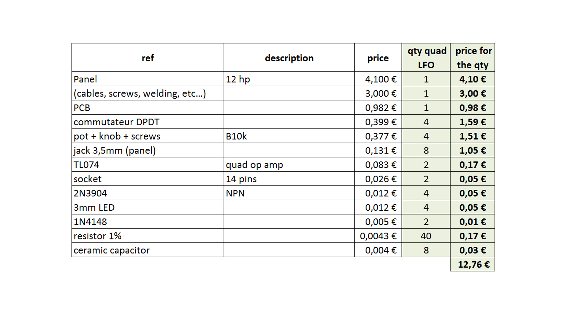
BOM :

- Clics : 2440
Avant la description, le fonctionnement général est à voir ici :
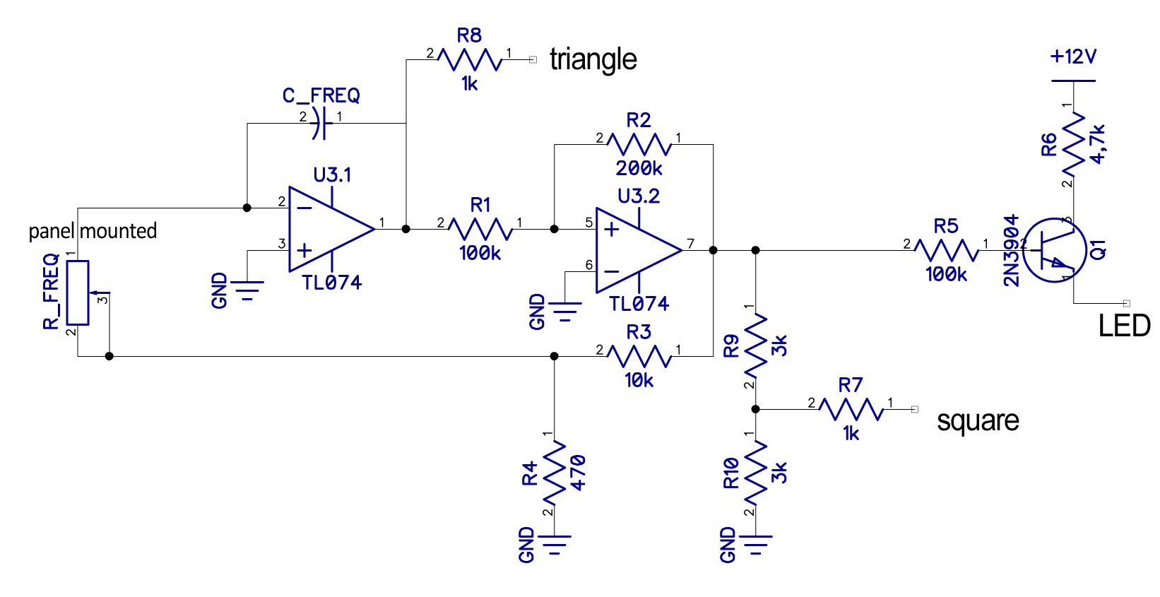
Schéma :
BOM :
- Clics : 2018
Avant la description, le fonctionnement général est à voir ici :
Et la partie mathématique est en vidéo ici :
Principe :
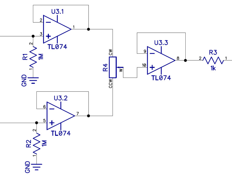
Le principe d'un attenuverter est le suivant :

où alpha est la position du potentiomètre, entre 0 et 1. Ce montage est équivalent à celui-ci :
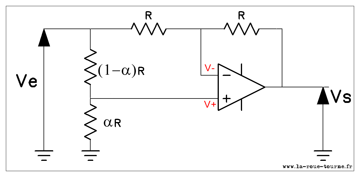
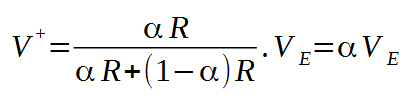
- en V+ :
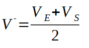
- en V- :
- pour un AOP idéal, on en tire :
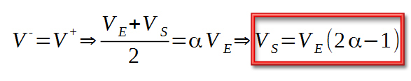
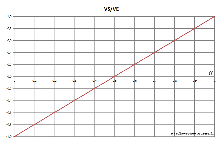
Cela donne bien la fonction de l'attenuverter :
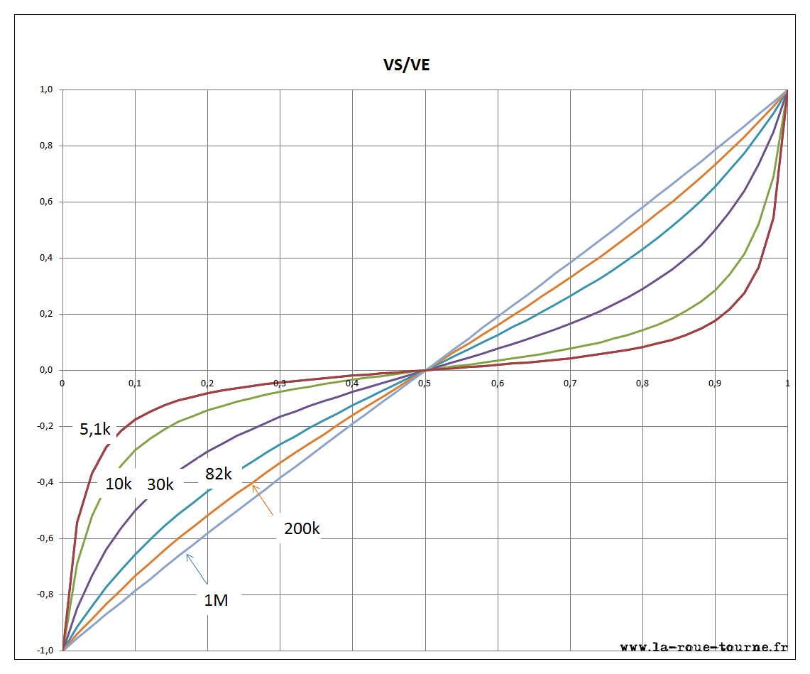
Le principe de l'attenuverter de précision est d'ajouter deux résistances identiques R' de part et d'autre du point milieu de potentiomètre :
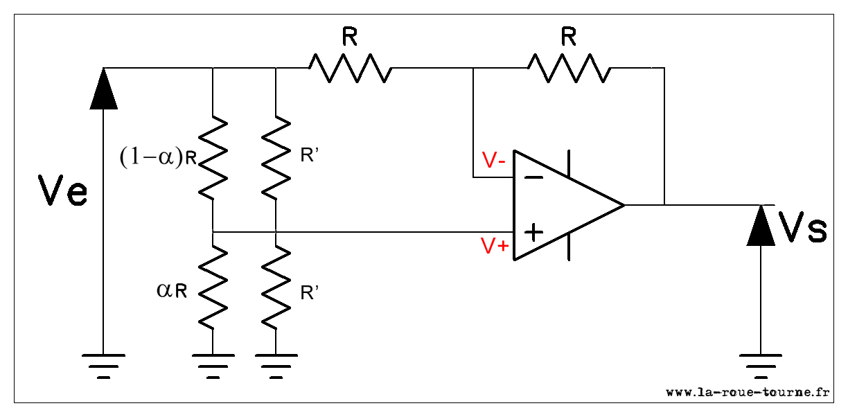
Ce qui est équivalent au schéma suivant :
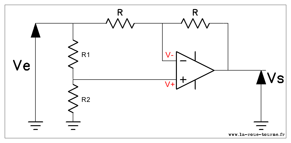
Où R1 et R2 sont les résistances équivalentes :
![]() et
et ![]()
Alors :
- en V+ :
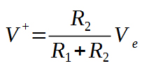
- en V- :
- pour un AOP idéal, on en tire :
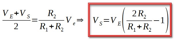
Cela donne bien une fonction différente de l'attenuverter, avec une sensibilité variable autour de la position médiane du potentiomètre, suivant la valeur de R' :
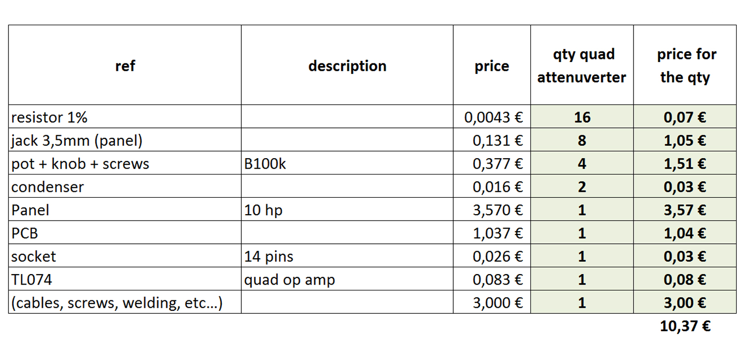
BOM
Moins de 20€ !
- Clics : 1749
Avant la description, le fonctionnement général est à voir ici :
Schéma :
Wiring diagram :
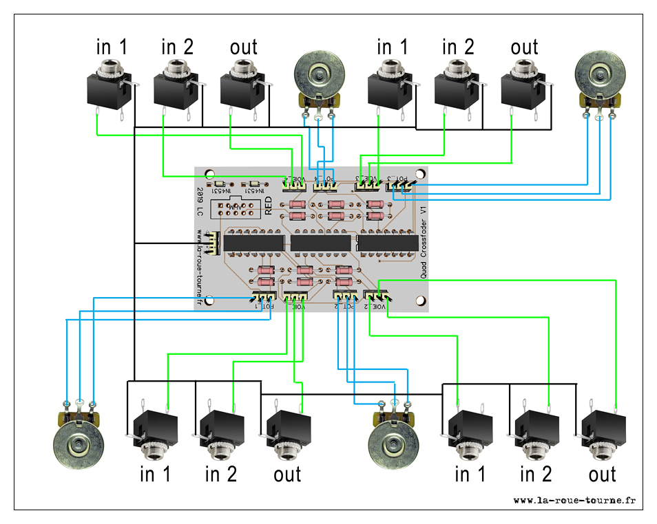
- Clics : 1293

Avant la description, le fonctionnement général est à voir ici :
|
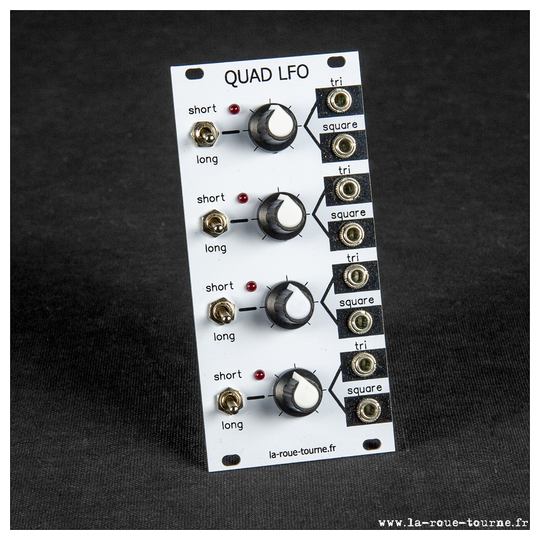
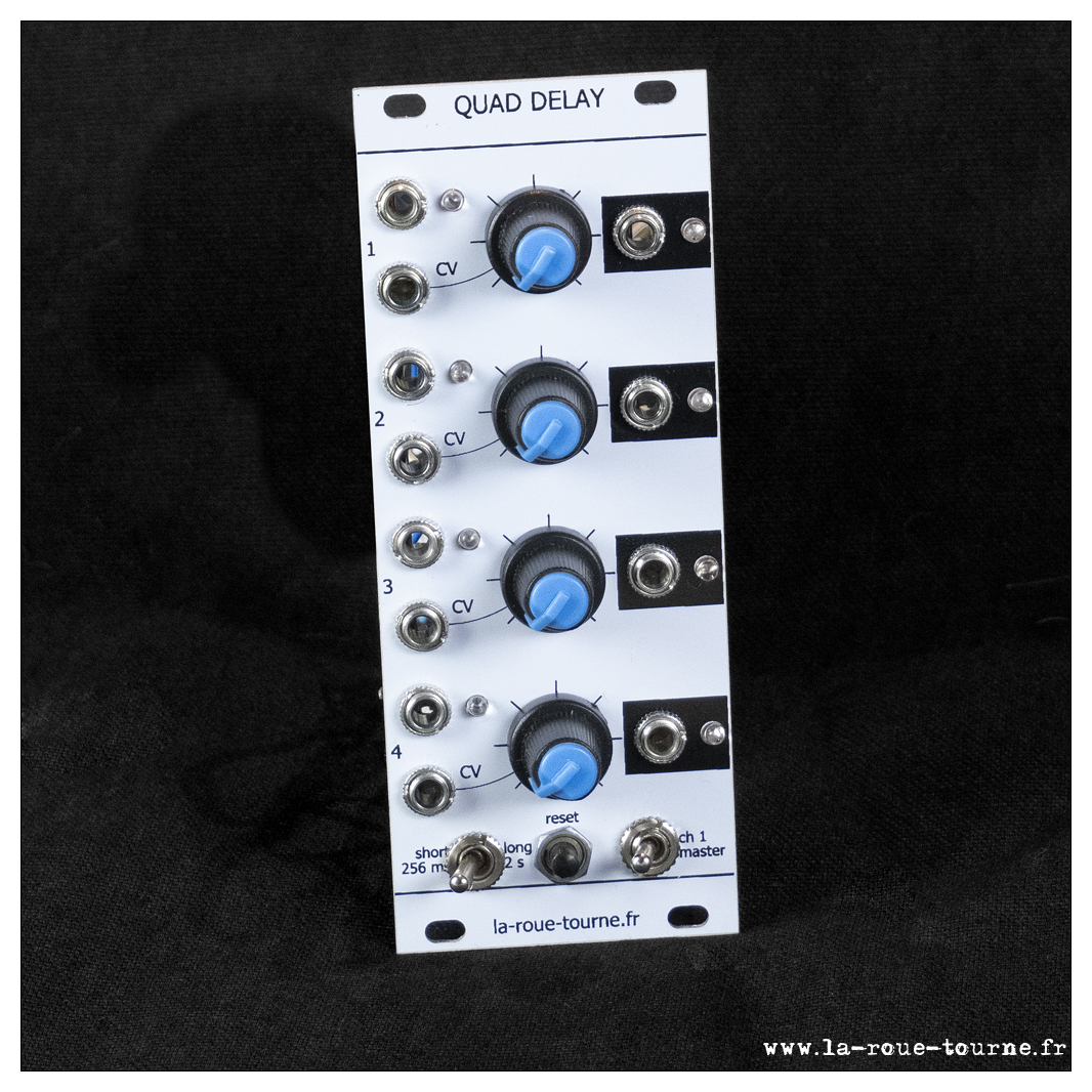
Le circuitA base d'atmega328 comme d'habitude.RésultatLe PCB : double face assez simple. Consommation : +12V = 25 mA ; -12V = 2 mA |
The circuitAtmega328 based as usual. ResultThe PCB: 2 simple layers. |


BOM
Code
- Clics : 1574
Plus d'articles...
Page 2 sur 3